Showing posts with label R3361B. Show all posts

Friday, January 14, 2022

Adventest R3361B Spectrum Analyzer vertical instability fix (failed joint between input LPF and coupler)

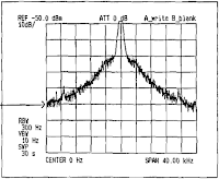
After full recapping of the PSU and CRT modules of my R3361B the instrument began showing a pronounced vertical instability: looking at the CAL signal (30MHz / -20dBm) the trace was randomly jumping up and down in a 5-8 dB range.
I initially suspected a side effect of my recent recappings, but that was not the case.

Long story short:
during recapping I was forced to move/dismount/rotate/drag the unit multiple times..
In one of these movements I had to drag the instrument towards me: the two front feet inadvertently went over the edge of the table; it has been as if the instrument had fallen from a height of 2/3 cm hitting the table edge right on its bottom front part.
This has been the actual moment since the instability began to show up.

Stated that:
- the input LPF-coupler assembly is located just behind the input socket in the right bottom front part of the unit - just where it took the hit;
- the LPF (THP118) and the coupler (THP202) are each built as gold stripes laid down on a ceramic substrate; the two parts are connected via a very thin solder joint crossing between the two ceramic wafers.. 

Sunday, December 19, 2021

Advantest R3361B Spectrum Analyzer CRT module removal and recapping.


DISCLAIMER: the following instructions are provided only as a report of my hobby experience. In NO way they can be interpreted as a replacement of the Advantest service  manual instructions. In no way I am responsible of any damage you or your device can suffer by following this procedure. Lethal voltages are present in the device!! Qualified personnel only! You know what you are doing and you are proceeding at your own risk!


Thursday, December 16, 2021

Advantest R3361B Spectrum Analyzer shows two side bands 10KHz apart from 0Hz (aka: PSU recapping)

I was having fun performing some modulation measurements on my sig-gen (HP8640B) by using my R3361B as a modulation analyzer ...when started to note a tedious 10KHz AM modulation on all signals, even in CW (I mean with all 8640's modulations settings turned OFF). Using a different S.A. I verified that there is no modulation whatsoever in the 8640's CW signals. The sig-gen is not the culprit.

So I went trough section 4.3.1 of the R3361B's service manual to check the side bands around 0Hz of my S.A. Pictures show what to expect and the actual I've got. It seems like my L.O. is AM modulated @10KHz making precise measurements (low SPAN and low RBW) difficult if not impossible..


The problem has been fixed with a full PSU recapping. Here is the result: