I was having fun performing some modulation measurements on my sig-gen (HP8640B) by using my R3361B as a modulation analyzer ...when started to note a tedious 10KHz AM modulation on all signals, even in CW (I mean with all 8640's modulations settings turned OFF). Using a different S.A. I verified that there is no modulation whatsoever in the 8640's CW signals. The sig-gen is not the culprit.
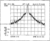
So I went trough section 4.3.1 of the R3361B's service manual to check the side bands around 0Hz of my S.A.
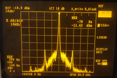
Pictures show what to expect and the actual I've got.
It seems like my L.O. is AM modulated @10KHz making precise measurements (low SPAN and low RBW) difficult if not impossible..
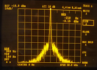
The problem has been fixed with a full PSU recapping. Here is the result:
Instructions to reach the Advantest R3361B PSU:
It is not so hard as it can seems at a first look..
You do not need to remove any board (learned the hard way...).
DISCLAIMER: the following instructions are provided only as a report of my hobby experience. In NO way they can be interpreted as a replacement of the Advantest service manual instructions. In no way I am responsible of any damage you or your device can suffer by following this procedure. Lethal voltages are present in the device!! Qualified personnel only! You know what you are doing and you are proceeding at your own risk!
- Leave the rig in its normal use position;
- Remove the four plastic feet on the back: the top and bottom metal covers will now slide off. You have to remove them both;
- Remove the left side rib - the one with the handle (4 big screws, 4 small screws); pay attention to the plastic termination at the back side of it: slide it off BEFORE attempting to remove the rib..
Now you see the PSU cage; - Remove 4 screws on top of the PSU cage. Beware not leaving washers and/or screws to fall down inside the rig (they ARE NOT magnetic).
At this point the cage top cover seems to be still fastened in some way but it is not. What is preventing you from pulling it off is some thermal conductive sticky grey material placed between the cover it self and the underlying PSU board heat sink. You can force it to come off making leverage by a large flat screwdriver. - Take note of wires routing and remove all 3 connectors: MAINs input, secondary outputs and FAN. Leave the yellow/black pair alone!
- Unscrew the 4 hexagonal turrets by mean of a hexagonal socket wrench.
The entire cage should now come off. - Unscrew 2 more small screws at the bottom side of the cage and you are done: the PSU board is now free to come out in your hands.
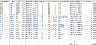
I strongly recommend you to recap it all.
Here is my recapping list including what I have found inside and what I have replaced it with:
Some useful Pictures:


Enjoy your S.A.
Emanuele.
No comments:
Post a Comment
Feel free to send comments