Thursday, October 26, 2023

My HP 6632 Power Supply has got crazy (SOLVED)

My 6632A s/n 3145A-06821


Symptoms:

  • power on is ok; no self test errors on the display;
  • VSETing from the front panel to values greater then 5/6 Volts triggers OVP.

Checks:

  • with these symptoms always double check the sensing terminals (S+ and S-): they must not be left floating. Be sure they are directly connected to output terminals on the rear terminal strip or to a remote load. For testing purposes mine were connected to the terminal terminals on the rear output strip;
  • checked OVP circuit as per SM: voltages at U110 are ok; both R158 and R155 checked ok.

Further investigation:
    • 0.1 Volts < VSETs < 4/5 Volts work but the readback (front panel) is out of, say, 15% and slightly unstable; the actual output is about 4x VSET and highly unstable: it jumps randomly up and down few volts.

NOTE: from now on I  connected my Arduino GPIB controller to the unit so that I can quickly issue commands to it without pushing the control panel buttons.
      
This is the result of “VSET 2” GPIB command:

The first spike is the direct consequence of VSET 2; the second is just pure random noise. Please note the rms voltage is more then 4 Volts instead of 2. The peak reached by the first spike was 20.4V, barely not enough to trigger OVP.

Friday, April 28, 2023

Graetz Joker-834 portable radio repair
What a challenge!

 This radio is as old as me: born in 1959.

Initial conditions

Found it in very tough conditions: dirty, smelly, not working (dead).
Inside the PCB was dirty and strangely greasy in some area.
I have found the schematic in my personal old paper archive.
Here is the annotated version I used during the repair job (look at the end of the article for a high res pristine version):

Please note this rig uses PNP transistors so GND is positive.
 

Sunday, February 26, 2023

Hard Disk catastrophic failure

Have you ever seen inside an hard disk that suffered a very strong catastrophic failure?

I don't: I've never seen something like this before....

The disk suddenly went in FAILURE status inside my server. 

Here is what I've found inside:


RAID saved me!

Ciao.
Emanuele.


Monday, February 20, 2023

Telefunken Italia - model "Mignonette MF" - 1a Serie

Telefunken Italia - model "Mignonette MF" - 1a Serie

JAN 2023 - restoration notes.

I don't want to bore you with information that is already available on the net about radio restorations and/or about this particular radio model.
I just want to share my restoration notes and annotated schematic.

This radio has the chassis directly connected to the power line.
There is a very HIGH risk of electrocution - use an isolation transformer when working with this kind of old radios.

Please note the use of an auto-transformer that imply no isolation from mains (!!) and as the power switch is directly connected to the power line. There is no fuse!
Everyone putting his hands into this chassis must know what he is doing!!

I started replacing all paper caps and the 3 electrolytics.
Then I replaced all the resistors that measured way out of specs. Some of them are unreachable (left alone).

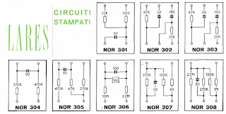
This Italian radio makes use of one of the first attempts to integrate components on a single "chip": they are LARES boards.

Here are few examples:

some LARES modules
Excerpt from LARES manual

Friday, January 14, 2022

Adventest R3361B Spectrum Analyzer vertical instability fix (failed joint between input LPF and coupler)

After full recapping of the PSU and CRT modules of my R3361B the instrument began showing a pronounced vertical instability: looking at the CAL signal (30MHz / -20dBm) the trace was randomly jumping up and down in a 5-8 dB range.
I initially suspected a side effect of my recent recappings, but that was not the case.

Long story short:
during recapping I was forced to move/dismount/rotate/drag the unit multiple times..
In one of these movements I had to drag the instrument towards me: the two front feet inadvertently went over the edge of the table; it has been as if the instrument had fallen from a height of 2/3 cm hitting the table edge right on its bottom front part.
This has been the actual moment since the instability began to show up.

Stated that:
- the input LPF-coupler assembly is located just behind the input socket in the right bottom front part of the unit - just where it took the hit;
- the LPF (THP118) and the coupler (THP202) are each built as gold stripes laid down on a ceramic substrate; the two parts are connected via a very thin solder joint crossing between the two ceramic wafers..