DISCLAIMER:
the following instructions are provided only as a report of my hobby
experience. In NO way they can be interpreted as a replacement of the
Advantest service manual instructions. In no way I am responsible of
any damage you or your device can suffer by following this procedure.
Lethal voltages are present in the device!! Qualified personnel only! You
know what you are doing and you are proceeding at your own risk!
To get to the CRT module I have followed this procedure:
- Place the rig in normal position.
Remove the four plastic feet on the back: the top and bottom metal covers will now slide off. You have to remove both. - Disconnect the black connector located in the backplane board very close to the PSU cage right front edge. It is the power and video signals BUS going to the CRT module.
- Remove the left side rib - the one with the handle (4 big screws 4 small screws); pay attention to the plastic termination at the back side of it: slide it off BEFORE attempting to remove the rib..
You do not need to remove the card reader board (if that option is installed). - Remove the plastic bar present on the upper crosspiece of the front panel and remove the 3 small screws that retain the front panel.
- Place the rig upside-down (from now on the left and right references are referred to this new position).
- Look at the front panel bottom crosspiece and remove the 3 small screws that retain the front panel.
You can now pull the front panel off but to completely remove it you need disconnect the ribbon cable from the controller board and the power wires from the power switch (take note of actual connections there..). - The CRT module is fixed to the main frame by mean of 4 screws located at the bottom side of the box (but you see them from the top as the rig is now upside-down).
Two are visible and reachable directly through two holes in the front panel lower crosspiece and the third is visible behind a group of wires close to back left side of the TG. Remove them all. - Unfortunately to reach the fourth screw you need to unlock the tracking generator. It can seems scary but then it is not so difficult...
- Remove the bottom front crosspiece completely removing 8 big screws; note that two of them are actually fastening the TG unit front part (just under the TG output connector..).
- Disconnect the flat cable from the back of the TG. 2 bigger and longer screws remain to be removed: they are located at the back left and right sides of the TG unit.
At this point the TG unit can be flipped over to top of the rig (..the bottom ...as it is upside-down) revealing that damned fourth screw. Remove it. - The CRT module should now be free to come off. Take care of all the wires while removing it.
- Once you have the CRT module in your hands, unscrew all the 8 small screws (4 on one side, 4 the on other side) but do not touch the 2 bigger screws you see on the lower back of the unit.
- At this point you can remove the entire CRT chassis out off the metal box.
- Should you want to separate the board from the chassis, disconnect the two wires bundles coming from the outside; disconnect the ground lead from the circuit at the CRT neck, unscrew the 4 nuts at the bottom side of the board.
You are now ready for recapping and redo solder joints.
Please note that C319 (10uF/25V)is a NON-polarized electrolytic.
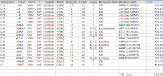
Here is the cap list I used for recapping:
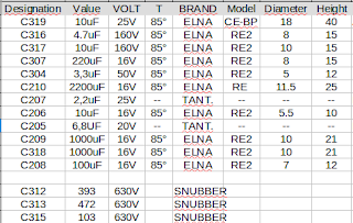
I've left C319, C207, C205 and all the snubber alone as I was not able ti find them at local suppliers and I din't want to wait for an online dealer..
Some useful pic:
 |
 |
Step 8.2: damn screw